
Direct answer: To size a fleet CNG station, calculate the gas vehicles need on a busy day, then distribute that demand across the actual hours when vehicles return and can remain connected. The busiest period determines the combination of compressor output, useful high-pressure storage, dispensers or time-fill posts, and acceptable waiting time. Finally, check gas inlet pressure and quality, available power, site circulation and the ability to maintain service during equipment outages. A vehicle count or daily total by itself is not enough.
The U.S. Department of Energy’s Alternative Fuels Data Center (AFDC) distinguishes time-fill, fast-fill and combination stations by their compressor and storage arrangements. Its infrastructure guidance states that fleet application, duty cycle, fuel use and fueling window affect station design. Those principles apply whether the gas comes from a pipeline or, in a separately engineered arrangement, a delivered CNG supply.
Why vehicle count is a weak starting point
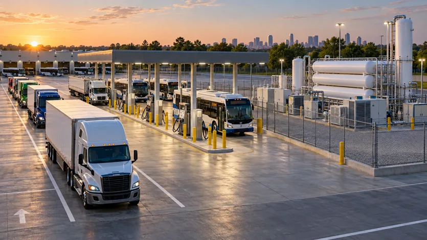
“Fifty vehicles” could mean 50 small service vans that each take a modest amount of gas and park overnight, or 50 heavy trucks that return in two waves and must leave quickly. The number says little about peak flow or the number of fueling connections required.
Create a vehicle-by-vehicle planning sheet. For each group, record vehicle type, tank service pressure and receptacle, daily distance or duty, average fuel used, high-demand-day fuel used, return time, departure time and desired fill method. If actual fueling records exist, use them. If not, state the assumptions and validate them with a trial or vehicle data before freezing the design.
A consumption estimate should be based on gas quantity or energy on a common basis. Some fleet records use kg, some use GGE or DGE, and some project specifications use standard cubic metres. AFDC gives a U.S. convention of approximately 5.66 lb of CNG per GGE, but any conversion to Sm³ depends on gas composition and reference conditions. Do not simply treat one vehicle tank’s water volume as its delivered fuel quantity.
Step 1: Determine the busy-day gas quantity
For each vehicle group:
Busy-day gas demand = number of fueling events × gas required per event.
Sum the groups and include other users of the station. Distinguish the gas purchased from the gas dispensed if compression, storage and system losses need separate accounting. A busy day may differ from the annual average; size service capacity for the agreed design day while using realistic utilization in the economic model.
Do not add a hidden percentage to every line. Identify each allowance separately: data uncertainty, fleet growth, equipment degradation or supply interruption. This lets the buyer decide what is required now and what can be reserved for expansion.
The existing fleet CNG system selection guide helps connect the operating pattern to time-fill, fast-fill or a combined layout.
Step 2: Map arrivals and the usable fueling window
The station’s true window is the time a vehicle is available to fuel, not the time the depot is open. A bus may return at 21:00 but be washed, inspected and moved before being parked in its overnight position. A delivery truck may arrive at 16:00 and need to depart at 16:30. Make a 24-hour table showing each group’s return, service and departure.
For time-fill, determine how many vehicles can be safely connected at once and for how long. If a vehicle parks for eight hours but can be connected only after two hours of maintenance, the usable window is six hours. For fast-fill, note the arrivals per 15 or 30 minutes, fuel needed per arrival and acceptable queue. A daily average hides the short surge that drivers actually experience.
AFDC describes time-fill as generally feeding vehicles directly from the compressor over a long period, with limited buffer storage, while fast-fill uses high-pressure storage to support quick transfers. Combination stations assign different vehicles to each path. The choice changes both equipment and operating procedures.
Step 3: Calculate period-average flow, then test short surges
Divide the gas assigned to a fueling period by the usable hours to obtain a first-pass average rate. That is a screening calculation, not a compressor purchase specification. Check whether most arrivals cluster at the start of the window. A 15-minute burst can exceed the hourly average, and storage or queueing may be needed even if the daily compressor output looks sufficient.
For fast-fill, ask for a sequence analysis: vehicle starting pressure, tank size, gas quantity, dispenser flow, initial storage pressure, compressor contribution and storage recharge after each fill. For time-fill, ask how the control system allocates compressor capacity across many connected vehicles and whether late arrivals receive enough gas before departure.
Define the service result. Is the goal to finish every vehicle by a departure deadline, keep the queue below a stated length, or deliver a minimum settled gas quantity? A vague “five-minute fill” target cannot be judged without vehicle and station conditions. AFDC notes that rapid filling raises tank gas temperature and can affect the settled quantity.
Step 4: Evaluate compressor duty at the actual gas source
Pipeline inlet pressure, gas composition and temperature influence compressor performance. Ask the utility for the minimum guaranteed inlet pressure and flow, not merely a typical value. Suppliers should state capacity and electrical power at the minimum, normal and maximum inlet pressure. Label pressure as gauge or absolute, for example barg versus bara.
If CNG is delivered by trailer, the trailer pressure changes during unloading and the station may need a daughter-station arrangement. That supply mode is a separate engineering decision from whether vehicles use fast-fill or time-fill. Ask for usable gas delivered per trailer and the compressor’s performance near the agreed trailer changeover pressure.
Gas quality can affect treatment needs. Obtain moisture and contaminant limits, composition and any requirements imposed by vehicle and compressor equipment. The inlet gas specification should be part of the request for quotation.
Step 5: Balance storage, posts and dispensers
Useful high-pressure storage can cover a short fast-fill surge while the compressor replenishes it. The storage vessel’s geometric size does not by itself tell the buyer how much gas is available at useful delivery pressure. Ask the supplier for initial and final pressure through a representative vehicle sequence.
Time-fill posts are a different constraint: a compressor may be large enough over the night, yet too few parking-position connections prevent all vehicles from fueling. Determine the number of simultaneous hoses, vehicle parking locations, manifold lengths and safe access paths. Fast-fill lanes need enough dispensers and room for vehicles to enter, fuel and exit without blocking the next arrival.
More equipment is not always the answer. Staggering return times, connecting vehicles for longer or separating overnight vehicles from urgent units can reduce a peak. These are operational choices that should be explored before the hardware is fixed.
Illustrative calculation: daily demand versus peak window
Assumptions only: A depot has 60 buses. On a busy day each needs an average of 45 Sm³, defined here as gas volume at 15°C and 101.325 kPa absolute. Total busy-day demand is 2,700 Sm³. Forty buses can be connected at time-fill posts for an effective six-hour night window, and each of those buses needs 45 Sm³. Their assigned demand is 1,800 Sm³, or a simple period average of 300 Sm³/h. The other 20 buses require 900 Sm³ at fast-fill dispensers around shift changes.
Suppose 15 of those 20 buses arrive in the first 90 minutes. At 45 Sm³ each, their combined demand is 675 Sm³, a first-pass average of 450 Sm³/h during that period. This does not mean the fast-fill compressor must be exactly 450 Sm³/h. Usable storage may contribute to the first wave and must then recover; short arrival clustering and dispenser count affect queue time. The six-hour time-fill branch may also call for compressor capacity at the same time. The supplier must model simultaneous operation.
If the 40 time-fill buses can remain connected for only four hours, their simple average rises to 450 Sm³/h. That change alone could alter the compressor and power concept. It demonstrates why the usable fueling window needs confirmation before requesting a fixed equipment quotation.
These figures are illustrative, not an HMZ delivered project or performance guarantee. Actual selection also requires vehicle tank conditions, inlet pressure, gas quality, temperature and local safety design.
A practical supplier comparison table
| Design input | Buyer provides | Supplier demonstrates |
|---|---|---|
| Vehicle and fuel data | Types, tanks, receptacles and gas per fill | Compatible fueling hardware |
| Daily demand | Busy-day and normal-day quantities | Supported operating schedule |
| Time-fill window | Number of connected vehicles and effective hours | Completed fills by departure time |
| Fast-fill peak | Arrivals by 15–30 minutes and maximum queue | Fill sequence and waiting estimate |
| Gas supply | Pressure range, quality and flow commitment | Compressor flow and power across range |
| Storage | Required successive quick fills | Useful delivery and recharge trajectory |
| Availability | Allowed outage and maintenance window | Redundancy and contingency plan |
| Site | Power, space and traffic routes | Arrangement, utility and civil interfaces |
Ask for both a P&ID and a general arrangement. An equipment list without a fueling-sequence calculation cannot show how the station serves the peak.
Site and expansion checks
Check turning space for the largest vehicle, access to each dispenser, pedestrian separation, parking-post hose routing, maintenance access, noise and utility capacity. A station might meet the flow calculation but fail to work safely within the depot’s traffic pattern. The local authority’s requirements may affect separation distances, electrical classification and emergency shutdown arrangements.
For growth, distinguish provision from installed capacity. Reserving a foundation pad, electrical feeder route or pipe connection can make expansion easier, but unused equipment purchased too early increases capital and maintenance cost. Ask suppliers to price a base stage and identified expansion options on the same assumptions.
RFQ questions that prevent undersizing
Request the proposed compressor duty curve, storage-use calculation, dispenser count, time-fill allocation method, electrical load list, gas-quality requirement, metering basis and control narrative. Specify the required outlet/fueling pressure for the vehicle systems and state whether all pressure values are gauge or absolute. If a flow is shown in Nm³/h or Sm³/h, state the reference temperature and absolute pressure.
Ask the vendor to identify assumptions about vehicle arrival times, starting tank pressures and simultaneous demand. Also clarify whether installation, civil work, power connection, training, commissioning and after-sales maintenance are in the quotation. An “installed capacity” number without these details is insufficient for procurement.
FAQ
Can I divide total daily demand by 24 hours to size the compressor?
That may badly understate the duty if vehicles fuel in a few hours. Use the effective fueling window and test the short peak, then consider storage and scheduling.
Does fast-fill always need a larger compressor than time-fill?
Not always. The answer depends on peak demand, storage and available recovery time. Compare complete operating scenarios.
How many dispensers should a fleet station have?
It depends on arrivals, fuel per vehicle, target service time and site traffic. Model the busiest sequence rather than using vehicle count alone.
Is storage capacity the same as usable gas?
No. Useful delivery depends on pressure range and the receiving vehicle condition. Ask for a sequence calculation.
When should delivered CNG be considered?
Where a suitable pipeline supply is unavailable or a project chooses road-delivered gas. Trailer logistics, changing inlet pressure and receiving equipment must then be included in the design.
Request a project-specific station concept
Send HMZ your vehicle list, busy-day fuel use, hourly return and departure schedule, gas source data, site plan and utility information. We can discuss a preliminary configuration and identify what is needed for an equipment proposal. Final sizing requires project-specific engineering.
Technical sources
- U.S. Department of Energy, Alternative Fuels Data Center, <i>Compressed Natural Gas Fueling Stations</i>: https://afdc.energy.gov/fuels/natural-gas-cng-stations
- U.S. Department of Energy, <i>Costs Associated With Compressed Natural Gas Vehicle Fueling Infrastructure</i> (2014), fleet size, duty cycle and fueling window: https://afdc.energy.gov/files/u/publication/cng\_infrastructure\_costs.pdf
- U.S. Department of Energy, Alternative Fuels Data Center, <i>Filling CNG Fuel Tanks</i>: https://afdc.energy.gov/vehicles/natural-gas-filling-tanks
- U.S. Department of Energy, Alternative Fuels Data Center, <i>Natural Gas Fuel Basics</i>, GGE convention: https://afdc.energy.gov/fuels/natural-gas-basics
Related HMZ CNG solution
Explore the related HMZ CNG product page for a project-specific configuration.
